|
Home
Parallel Computers
|
|


|
A Special Purpose Parallel Processor Using Multiple Parallax Propeller 8 Core Symmetric Controllers

Purpose:
I believe that the future of software is in parallel processing, either developing parallelizing frameworks for developers or
directly writing to multicore arrays.
We will start with a fixed connection topology initially a one dimensional vector or ring network and then move onto a 2 dimensional grid.
Future iterations of this work may use a small hypercube architecture (like the CM-2) that would have 2^n connections between processors providing us with O(logn) message propagation time.
How to build this parallel processor?
Until recently the only feasible alternative was to network pc's together in a cluster and use MPI software to communicate or rent time on a commercial supercomputer.
I did this in 95.409 back in 1999 on linux 486 systems.
When Intel came out with the Core 2 Quad, we were close but I was looking more for arrays of simple processing units (PE) or cells that can work together on a vector or matrix of integer data (I don't need floating point yet).
Two years ago I thought about the idea of connecting multiple basic stamp 1 chips together (the 14 pin single header version).
- as this chip met the design constraints involving power, board size and ease of use (no external components required).
However, the stamp is just too slow because of its' lack of assembly language support.
The parallel processing propeller chip will be what this initial vector processor will be based on
(at least until it is financially feasible to hook up 8-16 Playstation 3 processors into a cluster - congratulations University of Mass. Dartmouth).
We can also currently use the stream processing units inside recent graphics cards like the ATI 4650 which attains around 400 GFlops
using 320 vector processing cores to help out with Folding@Home.
Parallax Inc. has developed a very cost effective ($13) and extremely usable symmetric
multi-core processor chip (the propeller (c)) that contains 8 cores - each running at 20 MIPS with 2Kb of local RAM.
Using the 40 pin DIP version of this chip - it is possible
to design a small parallel cluster or matrix of simple computing cores.
This project will not build a traditional supercomputer, massively parallel (as in more than 16k processors) processor or be particularly time or space efficient.
The goal is to provide a parallel processing experimental platform on which to test the envelope of all the issues that surround connecting multiple propeller
multicore chips together on a single board or a combination of stacked propeller chips.
A secondary goal will be to test different configurations of linking multiple propeller chips together and how the internal 8 cores
will talk to the other sets of 8 cores distributed around the topology of a combination multi-chip/multi-core computer.
Goals/Requirements:
1) Applications
For myself Cellular Automata (Yes another Conway game of life or Wolfram CA) or,
Genetic Programming in hardware
The software that this cluster of nodes will solve must match the hardware as closely as possible in order to utilize all the processors efficiently.
The program and software are tightly coupled and designed together.
General purpose programs are very hard to parallize, I will initialy fit the program to the hardware. In cellular automata we can easily assign each cell to a processor.
with communication paths required only between adjacent processors. Therefore the architecture will be a connected array or a one dimensional torus.
2) Hardware
I would like to start with a simple cell based architecture using a 1 bit data bus
A speed of over 1000 MIPS
would be nice like the
(IBM/390 in 1998) but not even close to the 360 million MIPS machine being built this year in Toronto.
A good benchmark may be $/MIPS:
16 propellers (128 nodes)
= $(13x16 + 200 misc to build)/(20x128 MIPS)
= $408/2560 MIPS
= $0.16/MIPS
and the
UOT machine
= $50,000,000/360,000,000
= $0.14/MIPS
Looks like my processor is 15% less efficient at low quantities in a cost/MIPS ration as the biggest supercomputer in Canada - not bad since it costs only .0008% of the cost and can be built by one person using on average 1 hour per day in less than a year.
The Parallax Propeller will be the current platform of choice because of its
low cost, 8 embedded processors, multiple package configurations, low power and clustering ability.
3) Software Requirements
The key will be developing concurrent software that can execute on all the cores simultaneously.
I would like to avoid constructing an asynchronous cluster of processors that work independently on pieces of a larger problem and send their results back to a collector.
This parallell processor that runs on a layer of connected propeller chips would run sychronously in lockstep and execute a single operation on a piece of data sent out to each processor.
An issue will be the data setup of all the processors before letting them loose.
4) Education
Some problems lend themselves very well to parallization like grid algorithms, genetic programming and any type of vector processing.
I would like to create a custom parallel processing platform to investigate hardware and software issues surrounding parallel programming.
Part of the goal of this investigation is to eventually connect as many Parallax Propeller 8-core chips
together to form a massively parallel special purpose computer.
The term "massively parallel" is subjective here since i will probably be constrained to 128 or 256 connected processors
due to budget, power and fanout constraints.
Up until the recent past it was not really feasible to build your own parallel processor
I will start by simulating a cellular automata line or grid of cellular automata
(Either Conway or Wolfram encoded) and assigning each processor to a cell.
Disclaimer:
This will be an iterative process - attempting to maximize high performance, optimization or elegance of design
- at this point I would just like a platform to explore multi-core SIMD parallel design issues in hardware and software.
The number of cores I could use, I suspect ~ 128 or 2500 MIPS, will not really be a massively parallel machine like the original Thinking Machine 1
(the PHD thesis of Danny Hillis) which used 65536 processors in a 12 dimensional hypercube (16 processors at each node),
or the later CM-5 which used a tree based topology. I would expect a truly massive machine would be one with over a billion processing cells.
Why am I using the Parallax Propeller to build this fine grained parallel processor?
I was aware of Parallax single chip controllers since the Basic Stamp 2 at around 0.004 to 0.018 MIPS using interpreted PBASIC.
The basic stamp chip was very capable and was used to drive displays and run a Wolfram simulator but not really suitable for any performance or
parallel processing due to its low speed and single core and lack of assembly support.
However, the introduction of the multicore propeller controller completely changed everything because of its introduction of 8 multiple cores.
The ability to use assembly language at 20 MIPS/core (an internal clock speed of 80 MHz)
instead of its own interpreted SPIN language at 0.64 MIPS
(still SPIN is as fast as the speed of pure MC6809 machine language on my 1.1MHz 1981 TRS-80 COCO 1) is a great enabler.
In the desktop space I got an Intel Quad Core Q6600 and ran some benchmarks using some Java SE code and found that as long as
there was no disk access - multithreaded apps or 4 identical processes ran in the same time as a single process.
But there was no easy way to scale this experiment to 8 or more cores without using the propeller.
1) The ease of use when using the 0.1 MIPS SPIN interpreted language, the C compiler or direct machine language (20 MIPS) is like working with 8-bit machines from the 80's where you had control and understanding down to the operating system level.
2) The lower cost and no need of support chips beyond external EEPROM and possible bus transcievers
3) The low power consumption as opposed to using desktop CPU's
4) Deterministic properties of the Propeller because of the use of shared RAM semaphores instead of interrupts.
The propeller comes in 11 varieties that are easy to use with standard boards and breadboards.
A Discrete 40 pin DIP,
the Spin Stamp with 16 IO pins,
the Prop USB with 32 IO pins,
the OLED Prop with 4 IO pins (end of life),
the Prop Proto Board with 32 IO pins,
the Prop Proto Board with USB with 32 IO pins,
the Prop Rapid Proto Module with 32 IO pins,
the hydra game development system,
the Prop professional dev board with 32 IO pins and the
Prop demo board with 8 IO pins.
There is also the spin studio prop board with 32 IO pins.
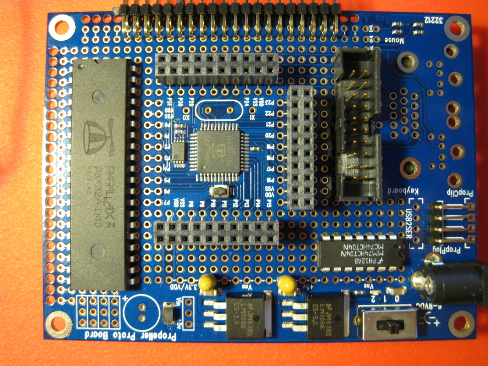
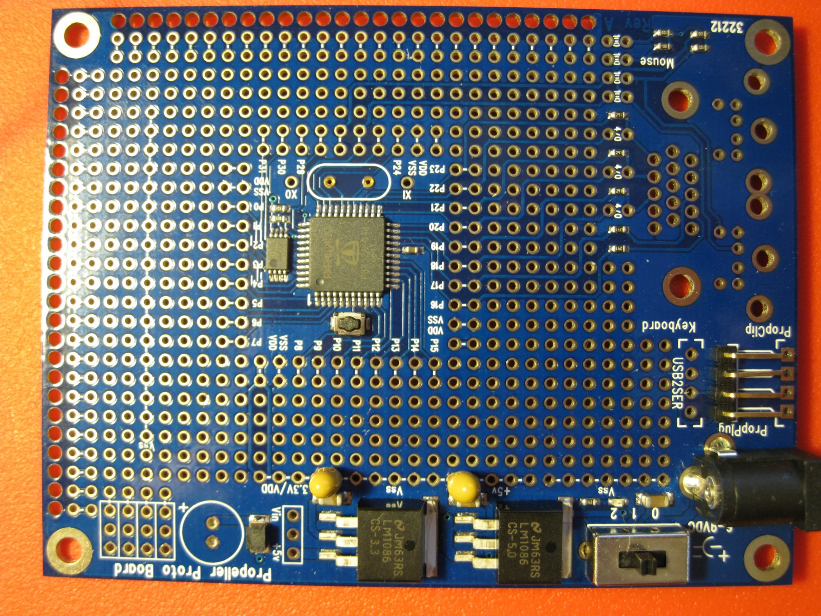
I will be using the Propeller Proto Board which is the most cost and design effective as it contains a complete
set of 32 to 28 available IO pins for connections to other propellers as well as the crystal, EEPROM and prop plug interface if required.
After an initial investigation using a single and later two propellers, I will be stacking propeller proto boards together in sets of 4 and possibly 8 boards.
The plan is to get to 128 propeller processors connected in a bus, line, array, hypercube or tree - whichever is the most feasible.
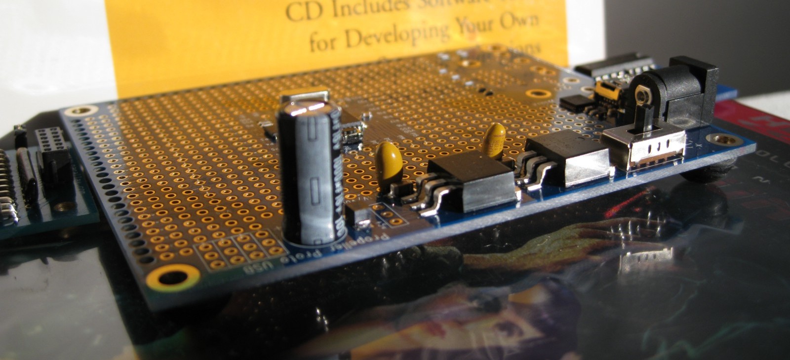
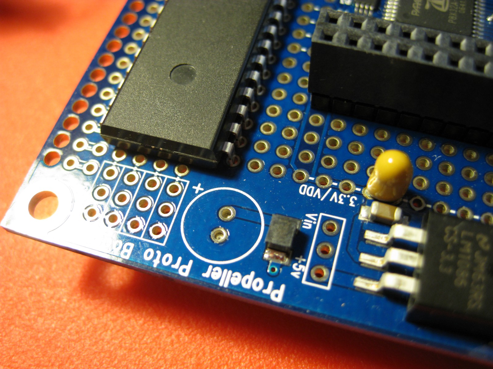
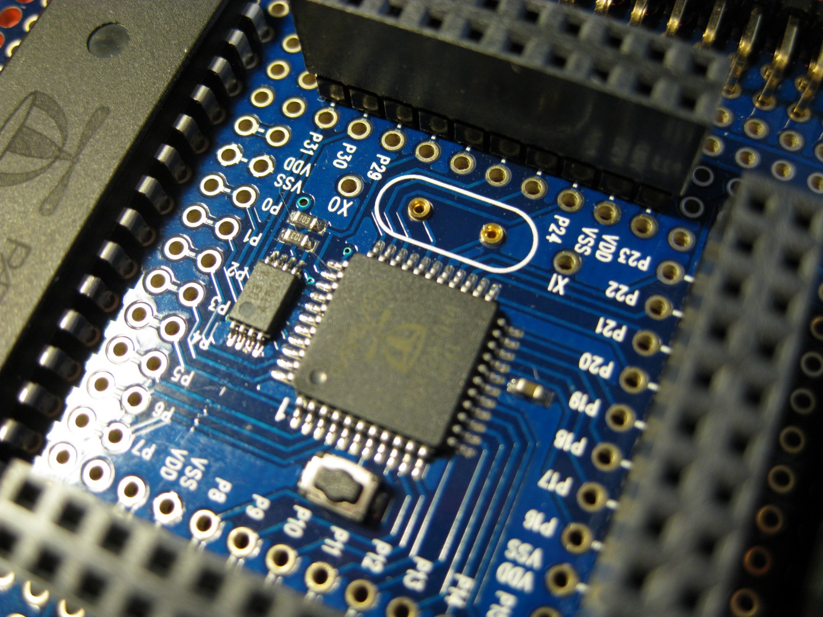
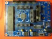
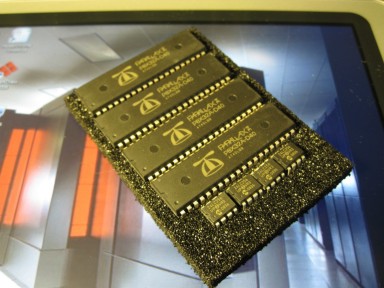
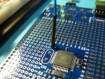
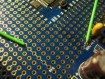
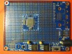
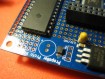
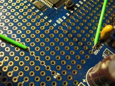
Here are some photos of the front and back of a new Parallax Propeller Proto Board USB showing all the space available for soldering.
There is also a profile shot of the proto board showing the nearly 1 inch capacitor that will require large standoffs if you plan to stack propeller boards.
|
|

|
Requirements Analysis:
| R1 |
PC Host Software |
Will be SUN Java software running javax.comm libraries on windows along with propellent.dll to
program the interfacing propellers. |
| R1.1 |
PC Host to Loading Propeller driver |
java software running javax.comm libraries on windows |
| R1.2 |
PC Host to grid-booting Propeller driver |
same software as the pc loader except that it is running on a different port |
| R1.3 |
PC Host Capture software |
same software as the pc loader except that it is running on a different port |
1) SIMD processing
Where a single program is run simultaneously on multiple cores on differing data sets. Ideally the code on each processor would be very short - no looping just a state change based on the state of adjacent processors in the case of a vector or grid topology.
  ' pseudocode
  nextStateThis := transistionSequence[prevStateLeft + prevStateRight + prevStateThis]
2) Loading and Preparation of multiple propeller chips
Issue: How am I going to load the same program on all the propeller chips from a single PC connection?
Connecting the USB port to each propeller chip is not really feasible.
I would also like to keep the chip count down by sharing an EEPROM for all or subsets of the propellers.
In reading through the Parallax propeller forums it seems that this issue has already been solved for me
by either resetting all propellers from a single EEPROM
in sequence, or using a bootstrap/host Propeller loader by Chip Gracey to
load all the others by serializing an internal version of the code to each propeller from a master propeller.
Decision
I will use three USB connections from a central PC host driver written in Java using the javax.comm API.
I have decided to use java instead of C as the host software because of my familiarity with all the auxillary API's that will be required
by this project including javax.comm and JNI for the PC to Propeller integration layer and JPA for the persistence layer.
3) Configurable Topology
The connections between the processors should be able to be configured as a hypercube, torus, matrix, tree or vector.
Here is a block diagram of a cluster of 8 cores on a single propeller chip - controlled by two cogs from a host propeller.
Here is a block diagram of a cluster of 16 cores on a two propeller chips - controlled by two cogs from a host propeller.
This is the block diagram of a single processing core or cell of a cluster of multiple propeller cores arranged in a vector or ring topology.
This is the block diagram of a single processing core or cell of a cluster of multiple propeller cores arranged in a matrix, or grid topology with optionally all sides connected as a torus.
This issue will either require a master propeller that controls a subset group of other propellers, or
one or more of the propeller cores must be dedicated as routers for the remaining 7 to 4 cores.
Another approach may be to add some external bus tranceiver logic around each propeller chip.
I suspect that I will need to use up some cores for communication with other propellers.
Since most topologies will require the number of cores to be a power of 2 - I will likely end up with
4 cores per propeller that are dedicated to pure parallel processing with the other 4 acting as controllers between
the rest of the core matrix outside each propeller chip.
A good connection strategy may be to add both a routing communication network and a hardwired left, right, north, south, up, down set of comm lines.
|
|
|
Experimentation/Prototyping:
I previously worked with the propStamp, propUSB, prop board USB, prop experimental board and OLEDProp96 versions of the propeller chip as single chips.
The goal is to start with 2 propStamps off a single 5v supply and link together via their 16 data pins.
I will then proceed to test linking multiple 40 pin versions of the propeller off a single 3.3v supply.
I would like to eventually stack 4 prop boards together using standoffs.
These prop boards should be able to hold additional propeller chips on the board or on daughter boards.
Ideally I would like to try 4 propeller chips per board on 4 boards for a total of 4 x 4 x 8 = 2 ^7 = 128 propellers.
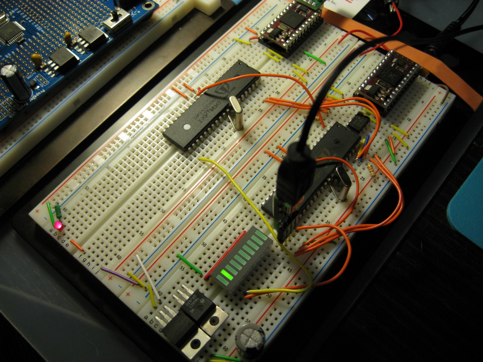
Two propeller chips running off a single EEPROM
The instructions by Christian and pems were a great help. I succeeded in running two 40 pin propeller chips off a single EEPROM.
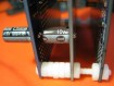
I slightly modified the procedure by toggling the reset pin of the second propeller instead of connecting it to a 10K ohm pulldown resistor (which only dropped to 2 volts for some reason under load).
I also used 2 separate 5MHz crystals temporarily until I construct a good clock source probably using 3 gates from a 74HC04.
Note: I accidentally powered up one of my 3rd propeller dips on unregulated 9V - I pulled the plug in 5 seconds.
Now when I re-power the chip it overheats in about 15 seconds until it is too hot to touch - I expect that I shorted some silicon inside the propeller chip - 8 more are on order. This is why using relatively inexpensive propeller cores over traditional Intel or AMD processors helps out as the propeller is relatively disposable.

Software: propCluster_phase0_1cog_2prop_c.spin
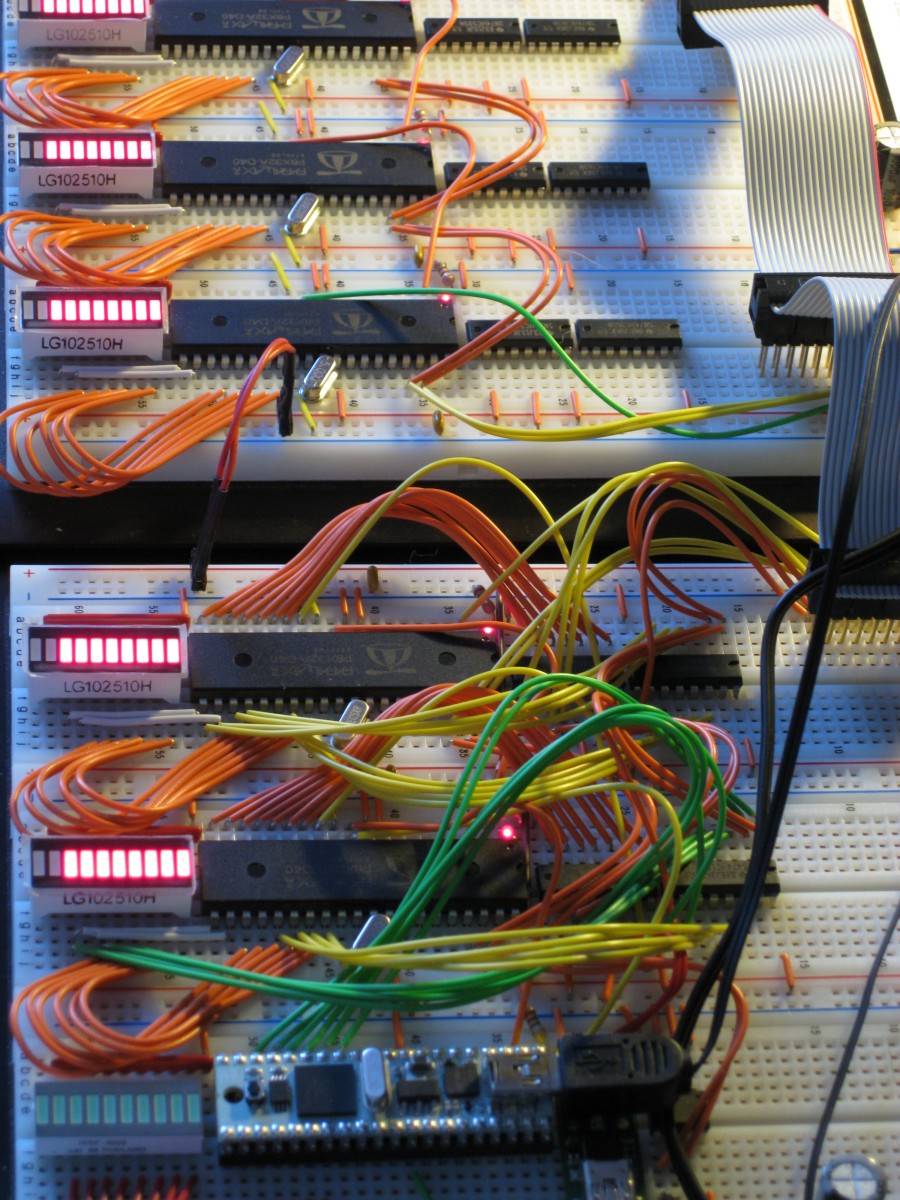
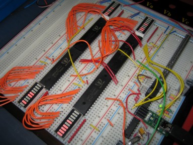
Four (4) propeller chips running off a single EEPROM using a shared external clock source:
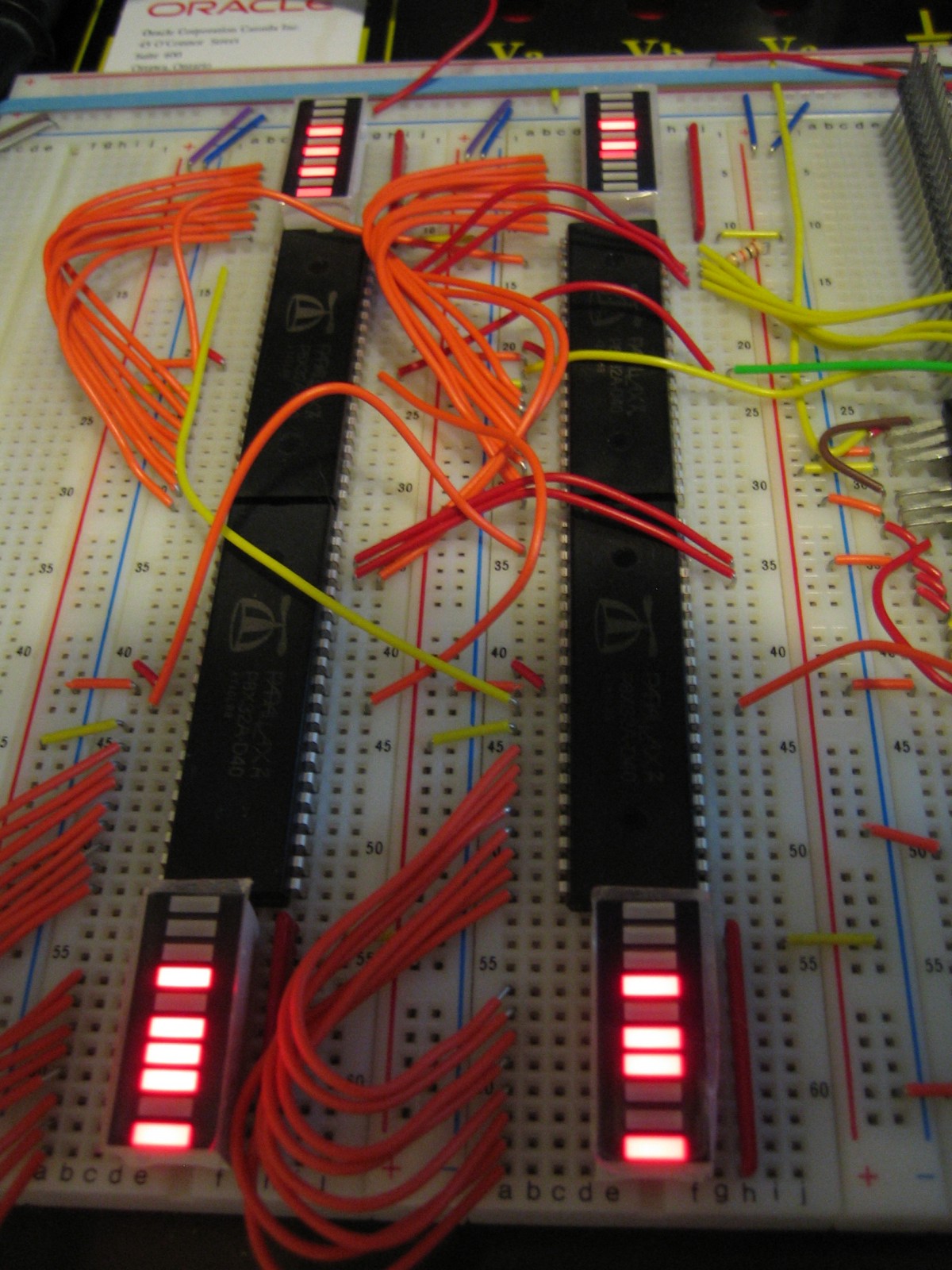
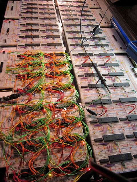
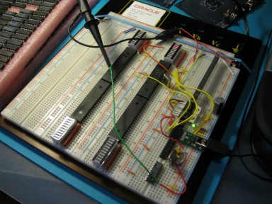
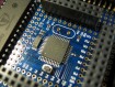
I start with 4 parallax propeller 40 pin DIP chips
And connect them in series to form a vector of 16 processors running in parallel (although I am only using 1 cog out of 8 so far).
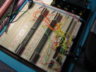
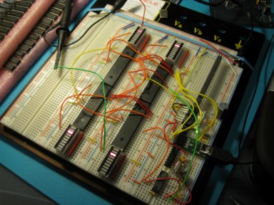
Realistically, all that has been done so far is to get four propeller chips to load off shared ROM and run in clock step.
The real work will be in working out the connection strategy between the chips and the assembly language routines.
|
|


|
Design Issues:
The following design issues surrounding running multiple propeller chips in parallel as a vector, array or hypercube need to be solved first.
MIMD vs SIMD
Clock Propagation, Synchronization and Drift
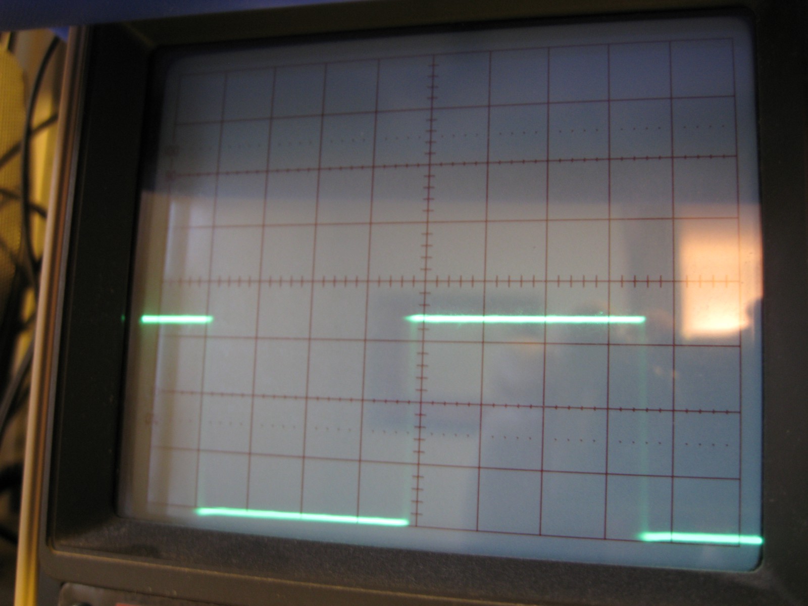
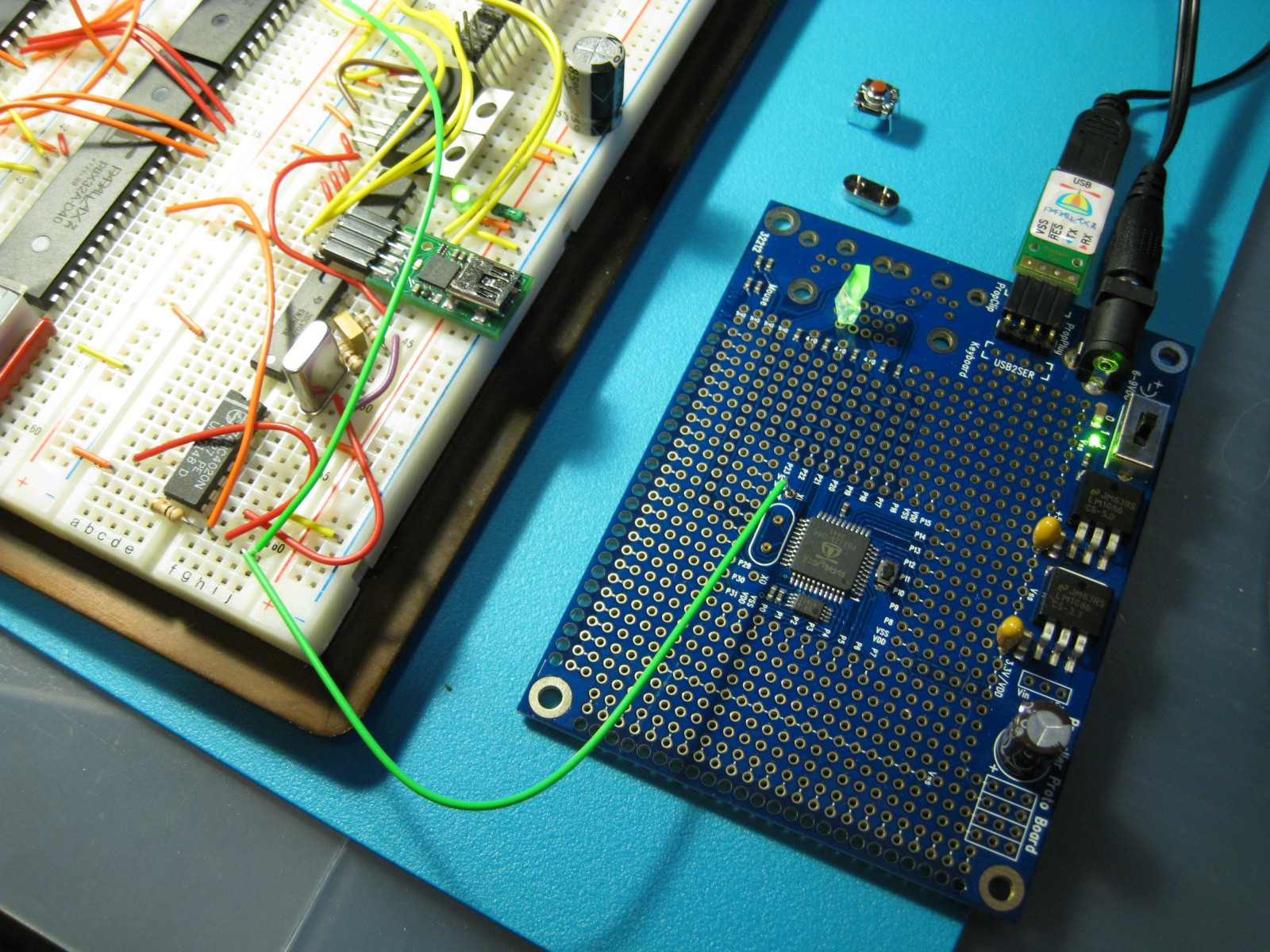
20081213: success connecting an external clock running from 3 inverters from a 7404 series 5V chip (I haven't tried a more appropriate 74HC04 yet)
I removed the external 5 MHz crystal and connected the output of my oscillator circuit to XI on the proto board.


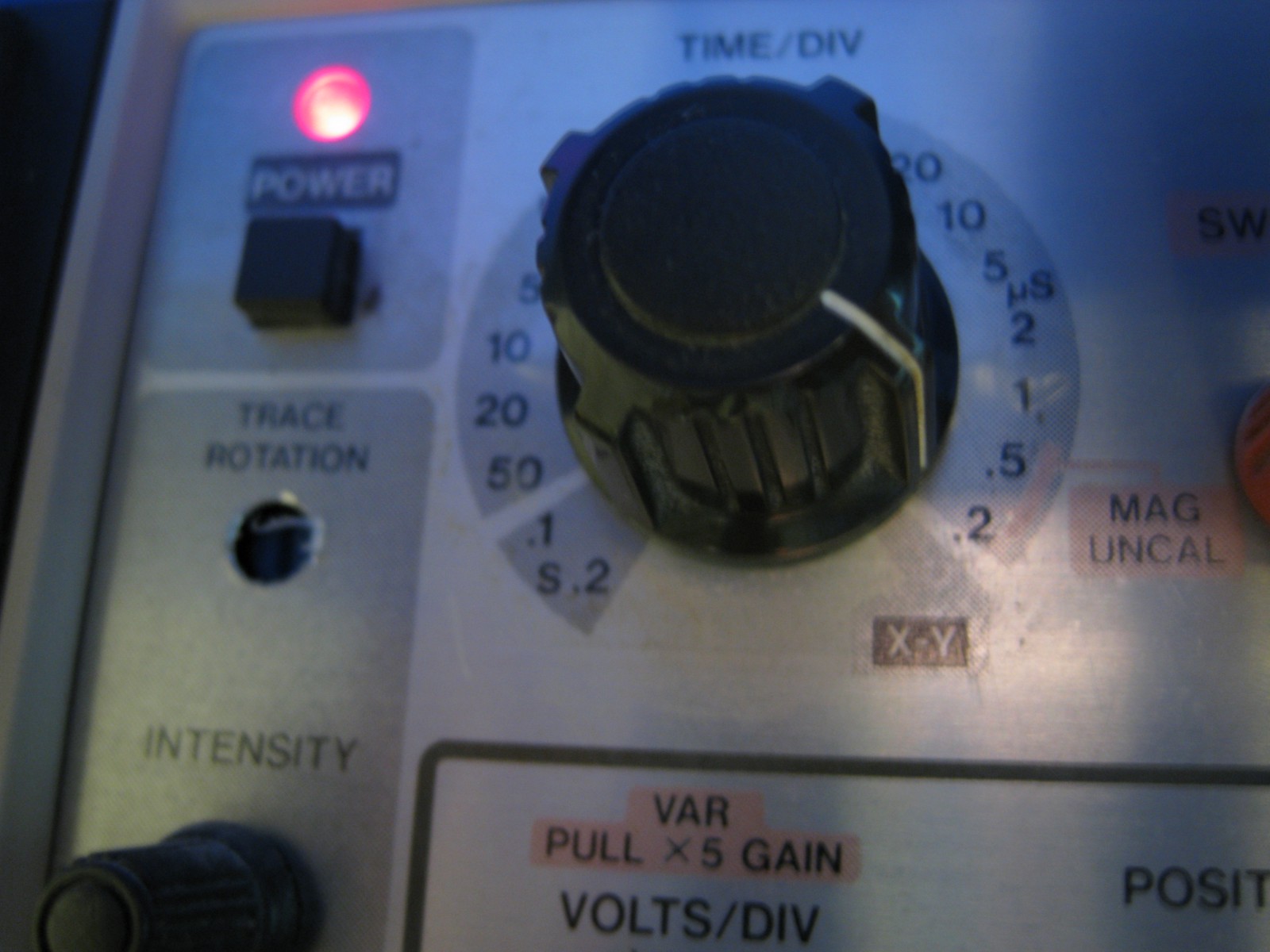
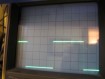
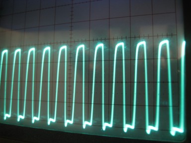
As you can see in the following capture from an (analog) 20 MHz oscilliscope - the output of an external clock source is 5MHz (i am using the crystal that I removed from the propeller proto board.
The signal is relatively clean and even though it is around 3.9 volts - it drives 5 (five) propeller chips fine (4 DIP and 1 proto board).
See the 0.2 uSec division and the waveform signal that is fed into the XI pin on the propeller proto board.

Sharing an external clock signal among multiple propeller chips
This is feasible, I have removed the external crystal from a prop board and driven the XI external crystal input off of
my own oscillator on a breadboard. I have been able so far to drive four propeller chips of a single inverter.
When I am able to connect eight propeller chips I may have to distribute the clock through a couple buffers before connecting clocks to the propeller.
Bus based or connection based topology or both
Power Constraints
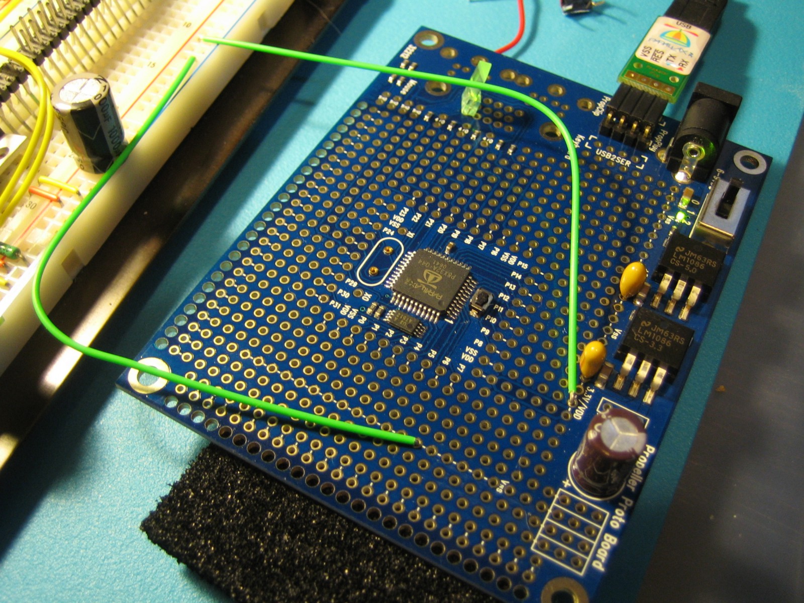
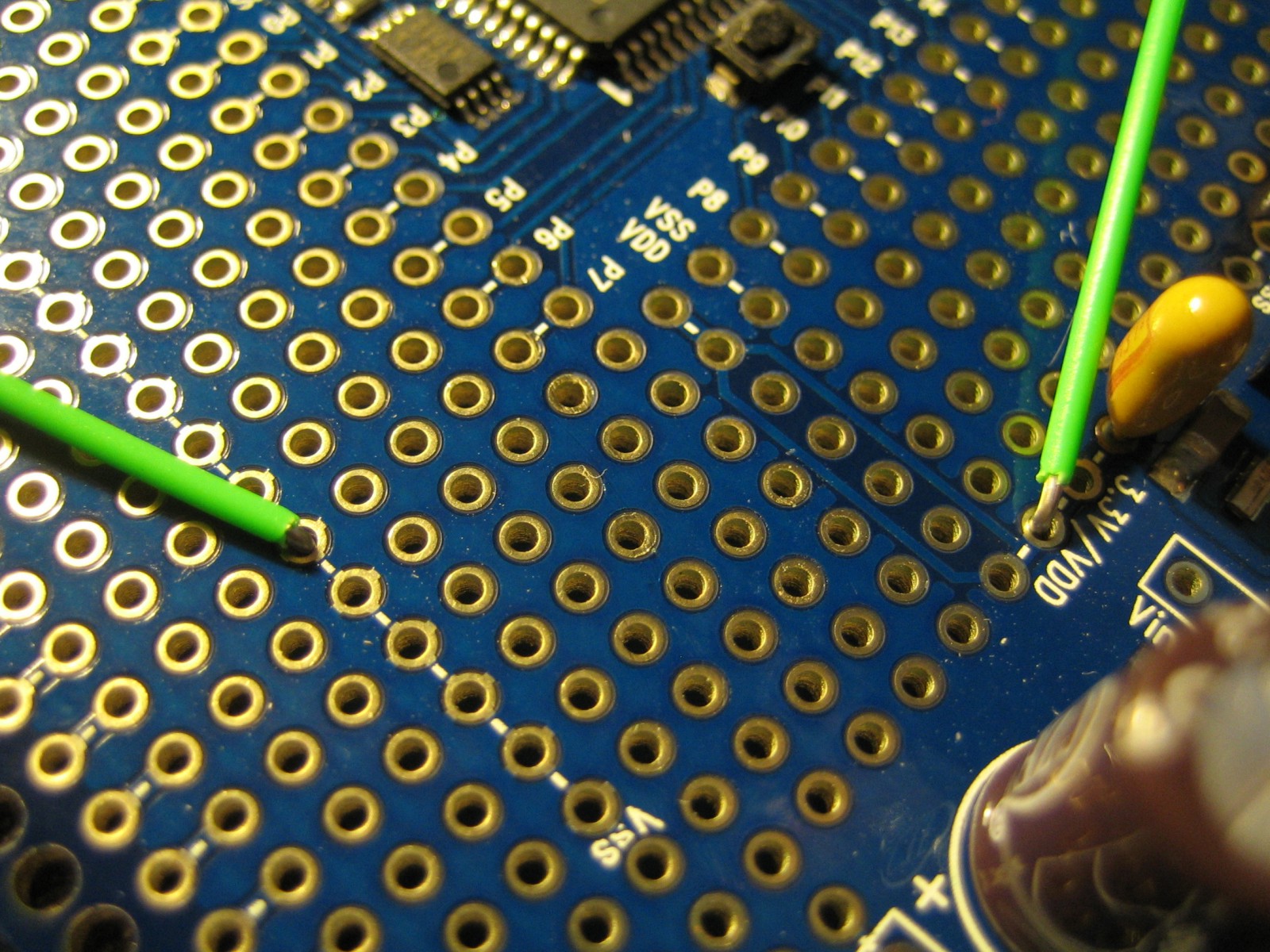
Shared power among multiple propeller proto boards:
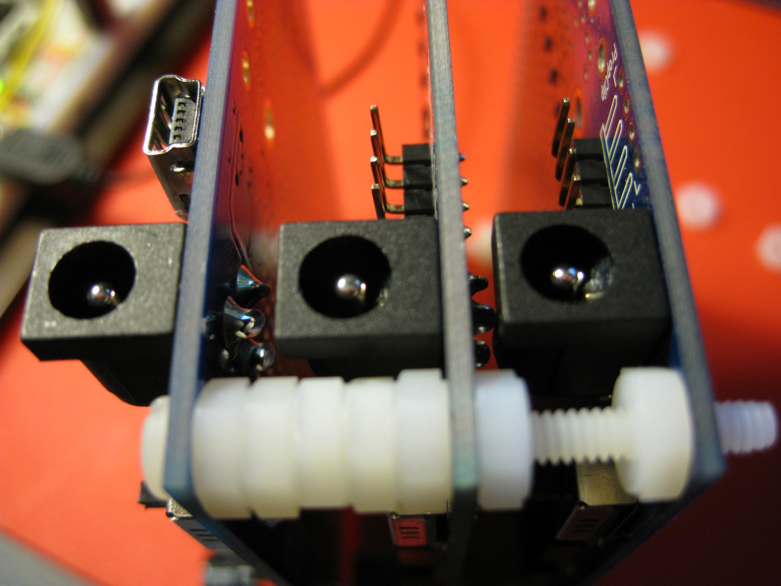
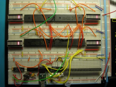
20081213: I had success connecting propeller prop board to external power off of a breadboard.

Here we run three propeller proto boards off a single supply by putting jumpers on the VDD/VSS rails - alternatively we can run VIN to each board and let its' own 3.3v regulator supply power.
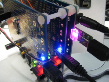
I also removed the 10V (16V on the proto board USB) 1000uF capacitor from the servo power section on the proto board - as we do not need it for pure parallel processing. Note: we do need at least 1 capacitor on the 3.3v supply from the 2916 so that we do not get voltage harmonics above 3.3v.

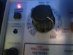
20081215: I have run into some issues when running multiple propellers (4) off of the same default 7.5V power supply through a
3.3V power transistor with an output of 500mA.
At first I thought that it might be the 32 LEDs using 220 ohm rails, but the power transistor stayed hot even when all LEDs were removed.
It turns out that the clock speed of the propeller chip is directly proportional to its power dissipation.
If I keep the clock multiplier below 4 times (PLL4X) then the power transistor does not overheat without a heat sink.
Here is some Propeller SPIN code that runs the same object on all 8 cogs.
Notice that the bootstrap processor (cog 0) first loads all other processors on-chip 1-7 and then itself.
The issue is that all the 8 cogs are running a little bit behind each other (in sync)
- we will therefore need an external sync signal - probably from a master propeller chip.
PUB Main
  ' Toggle RESET_OUT immediately so we can cascade programming other propellers
  outa[RESET_OUT] := 0
  outa[RESET_OUT] := 1

  ' Load all other 7 processors on-chip first
  cognew(Process(1, COG1_STATE, 0), @regStack1)
  cognew(Process(2, COG2_STATE, 0), @regStack2)
  cognew(Process(3, COG3_STATE, 1), @regStack3)
  cognew(Process(4, COG4_STATE, 1), @regStack4)
  cognew(Process(5, COG5_STATE, 0), @regStack5)
  cognew(Process(6, COG6_STATE, 0), @regStack6)
  cognew(ProcessEdgeCog(7, COG7_STATE, COG7_IN,COG7_OUT, 0), @regStack7)
  ' load current processor 0 last
  ProcessEdgeCog(0, COG0_STATE, COG0_IN,COG0_OUT, 0)

PUB ProcessEdgeCog(processorNum,lStatePin,propInput,propOutput,initState)
  ...
  Process(processorNum,lStatePin,initState)

PUB Process(processorNum,lStatePin,initState)
  ...

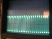
Short 15 Mb video of 32 processors (cogs) of a 4 propeller system running (no interpropeller connections yet)
We have heat issues (we will need distributed power).
We also have timing issues (all cogs will need a common sync after initial programming of ~2 sec per propeller).
- at both the cog level and inter-propeller level..
I tried running at PLL16X and held the power transistor on the propeller breadboard - it heated up in about 5 sec.
I had to pull the plug because of the on-occasion EEPROM programming error (F11).
I tried PLL4X and after about 2 min i needed to remove my finger on the 3.3V power transistor.
Result: PLL2X (10 MHz or 2.5MIPS per processor) is the maximum sustained clock speed without using a custom power supply
Physical Design Constraints
74HC Fanout Constraints
The spec says that 4 inputs can be driven by a single output without pullup resistors.
Processor Communication on chip vs off chip
|
|
|
TimeLine:
20081201: Project started with 2 propeller 40 pin dip chips
I will also refer to the investigation by
(Christian de Godzinsky in Finland on using a single EEPROM for multiple propeller chips) and (pems) as well as programming multiple propellers from a single USB serial port.
20081202: Ordered 15 more prop proto boards - during the 10 days until they arrive I will investigate inter-propeller connection strategies using the 40 pin version.
20081205: spent an hour hooking up two 40 pin dip propellers using Christian's instructions - both propellers run off a single EEPROM - thank you.
20081209: received my extra 40 pin dip propeller chips and all my propeller proto boards - have to say that the Parallax Sales dept is exceptional.
In the process of hooking up an external clock source to the XI pin on the propeller
20081210: success connecting four (4) propeller dip chips together running off a single EEPROM on a shared external clock
20081213: success connecting an external clock running from 3 inverters from a 7404 series 5V chip (I haven't tried a more appropriate 74HC04 yet)
I removed the external 5 MHz crystal and connected the output of my oscillator circuit to XI on the proto board.
20081213: success connecting propeller prop board to external power off of breadboard - we will be able to stack prop boards so that all share 3.3V power from one of the boards.
I also removed the 10V (16V on the proto board USB) 1000uF capacitor from the servo power section on the proto board - as we do not need it for pure parallel processing.
20081215: I have four (4) propellers running with 32 active cogs running the same program - there are some power issues when running 4 propellers off the default power supply at high frequencies.
20090102: I don't remember where on the forum I saw this but there is a way to run multiple ports and propeller IDE's by doing the following.
- in Preferences | Files @ Folders | Associated files launch into single editor = false
- when you run each Propeller Tool IDE, connect a single propeller USB port at time, identify (F7) and disconnect
- do this in sequence for all your USB ports (I am running 3 simultaneously)
- when done reconnect all usb ports, the ports will survive a power down
20090104: I built two prototypes to run the PropellerLoader.spin bootstrap object by Chip Gracey - see a small issue I had on the Parallax forum.
The beauty of this loader is that it can load software in RAM to other chips before they reference their EEPROM which allows us to cluster the prop proto boards.
The PropellerLoader.spin object also does not require code on the target chips - it only needs a host controller
20090106: Success using the SUN javax.comm Communication API with Windows.
In the past I developed direct port drivers for the PPT and SER port using VisualStudio 6, I could not get the SUN Comm API to work outside of Linux.
However, I came across a page by Rick Proctor for the Lego RCX Brick at http://dn.codegear.com/article/31915
and at http://llk.media.mit.edu/projects/cricket/doc/serial.shtml
which explains how to setup and implement the SerialPortEventListener interface.
20090107: Decided to use Christian's method of running multiple chips from a single EEPROM - the load times are the same as for the PropellerLoader object.
This approach will use DIP versions of the chip.
The EEPROM based loader will require bootstrap code on each cascading chip - that can later be replaced by the core code.
20090115: Overheating of the 3.3v power transistor was because some connections between propeller chips were input->input via software.
A good heat sync is a 1 inch brass standoff.
20090131: Succeeded in getting 5 propeller chips or 40 nodes connected and running off a single EEPROM, see the
post on the Parallax forum for the multiple boot design pattern.
It turns out that we see a load time of 1.5 seconds per chip, I had a 5 second load time for a while on one propeller because I was inadvertently grounding the crystal.
20100416: 3-dimensional Hypercube topology including NEWS connects for an 8-chip (32 core @ 4 per chip) network prototyped.
|
|
|
References:
The following references are to sites that I found helpfull and discovered during the development of this parallel processing project.
Parallax Propeller Multi-core Controller Data Sheet - Rev 1.1 9/12/2008
Parallax Propeller Multi-core Controller Data Sheet - Rev 1.0 11/14/2007.
Parallax Propeller Multi-core Controller Data Sheet - Rev 0.2 4/2/2007 - for historical reference.
Parallax Propeller Multi-core Controller Quick Reference - Rev 1.5 10/19/2007
http://www.parallax.com/dl/docs/prod/prop/WebPM-v1.01.pdf
Parallax Propeller Lab Setup.
UController.com : Machine Language on the Parallax Propeller Tutorial.
Danny Hillis - one of the first pioneers of Massive (65K+ processors) parallelization - the TM-1 consisted of cabinets of arrays of boards containing arrays of chips that contained 16 1-bit integer processors in a hypercube topology.
Multicore Processors on Wiki
The Transputer
- Occam 1 has parallels to Propeller SPIN like its VAR support and off-side indentation
The Parallax Propeller 8 core processor on Wiki
Parallax Propeller Forum threads
Future propeller II
Future propeller II
Propeller loader by Chip Gracey
Parallax Forum: Multiple Propellers & one EEPROM
Parallax Forum: Parallel Cluster based on the Propeller
Parallax Forum: Parallax Supercomputer
Propeller Tricks & Traps (Last update 21 June 2007)
Propeller Machine Language
Two usb connections
SparkFun Electronics Forum: Parallel Cluster of Microcontrollers
hackaday.com : An example of a custom 8 processor array using PICs
IRobot Create
Parallel Computers
CMU
SuperComputers
computerhistory.org
A good description of how parallelism was effectively used in insurance processing before we had electronic computers.
Hardware knowledge is beneficial to high level programming - IE: thread segmentation and synchronization
Here is an article I found by accident in an old issue of Byte magazine from exactly 20 years ago in Nov 1988 that discusses parallel processing machines including the Inmos Transputer.
- Warning: 17Mb in around 2 min.

Pinouts:
74HC4020 14 stage ripple counter
|
|
|
Resources:
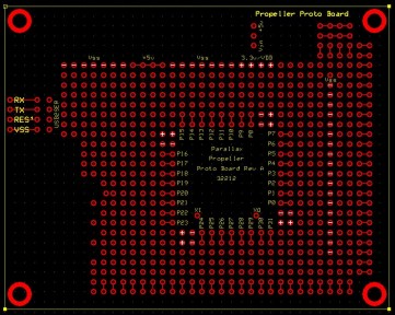
To aide in laying out a design for the Parallax Propeller Proto Board (propclip or USB version), I find it very helpful to have an ExpressPCB layout to work with.
I have searched online for a proto board PCB file but could not fine one. Here is a blank propeller proto board PCB file that I hope you find usefull.
Disclaimer: I have tried to replicate the board dimensions and standoff holes on the propeller proto board as accurately as possible but the edges of a board manufactured
using this layout may not line up exactly on top of a board from Parallax Inc. (yet).
Parallax Propeller Proto Board ExpressPCB file - Rev 0.8 21/12/2008
|
|